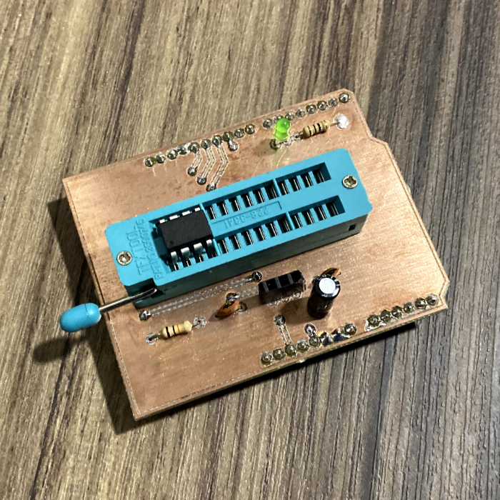
Burner Shield for ATMEGA328P/8L and ATTINY85
Posted on February 24, 2020
The problem
Recently I made a PCB to control a step motor with a liquid crystal display and some buttons, and for that I decided to utilize an ATMEGA328P because of the large usage of memory by the libraries and because of the quantity of pins I'd need to use. Since the PCB was conceived for a very specific use, it wouldn't need the programming pins exposed (be it ICSP or the FTDI pattern), but the tests I made in the bench would only allow me to test the steps it was programmed to follow and the tests of torque and actuation speed could only be made in the PCB, with all the pieces installed.
The ideal motor speed configuration took too long to be found, having been necessary to remove the microcontroller off the PCB to an Arduino and back again too many times, at the cost of damaging a pin or even the 28 pin socket. So since that day I imagined the shield board of this post, for me to be able to program any microcontroller I usually use (an ATMEGA328P, or ATMEGA8L or an ATTINY85), without the need to make the connections in a protoboard and without the risk of damaging something in the process.
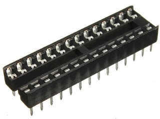
28 pin DIP socket. Source: MakerHero
Making the PCB in EAGLE
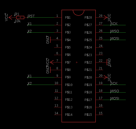
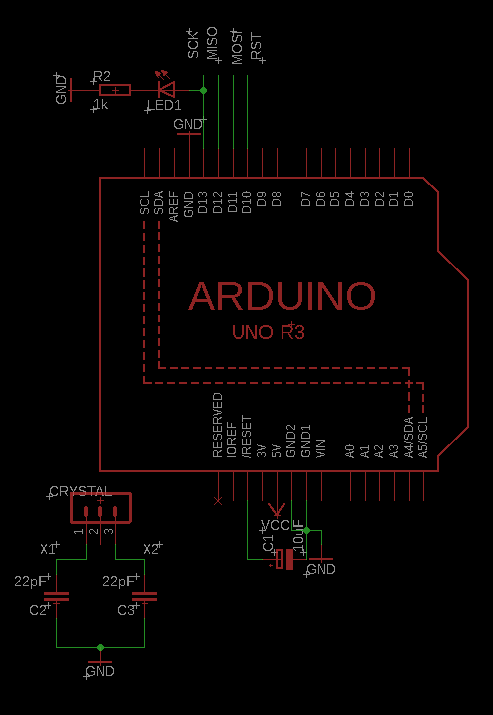
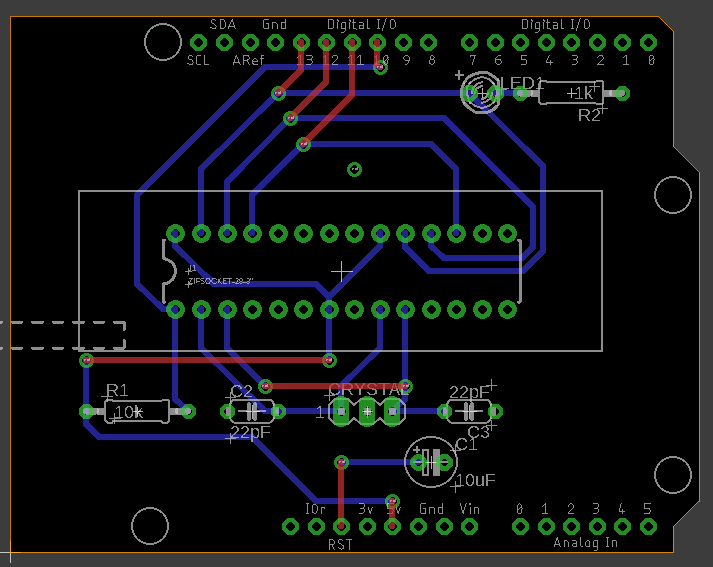
To make the PCB in EAGLE I used the Arduino Uno R3 schematic made by Adafruit (here's the link for the library), I planned the necessary connections to make the programming via ICSP, on both the ATMEGAs and ATTINY. I also exposed the crystal connections, in order to burn the code already at the frequency I'd want to utilize. I added an LED to the digital pin 13 to visualize the programming process.
The ZIF (zero insertion force) socket compatible with what I had come from the SparkFun-Connectors library, made by SparkFun.
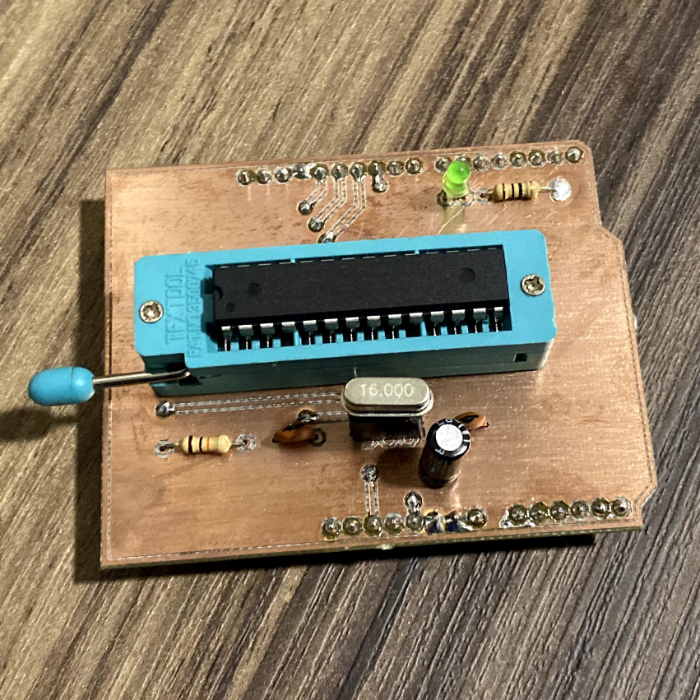
PCB ready
I submitted the EAGLE-generated files to the ProtoLab website, a fast prototyping laboratory where I once had a scholarship. I gave them the dual layer fiber board and I soldered everything to it afterward.
Download
To download the EAGLE files, here is a link to my GitHub repository.
