USB Board for Raspberry Pi Zero
Posted on December 16, 2025
This post depicts a prototype project made on commission for a company, so there was a commercial relationship between the parties involved. Some sensitive information has been omitted for confidentiality reasons.
Project Challenge
I was introduced to this client's project with the proposal to solve a problem that seemed simple: extract photos from a camera and transfer them to their mobile application. In the original situation, the user would send a WhatsApp message when starting a photo capture session to register the time, and after their shift, someone would check the photo capture time against the sent message to match the location registered by the application with the camera's photos.
After some discussions about requirements and the actual needs of the prototype (summarizing to keep this post brief), we decided to use a Raspberry Pi Zero 2 W running a program to extract photos from the camera via USB and send them to the user's phone using Wi-Fi. Additionally, the Raspberry would be powered using a powerbank, and a GPIO pin would be responsible for turning the camera connection on and off.
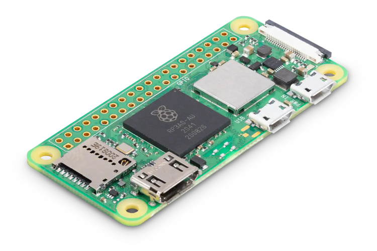
Raspberry Pi Zero 2 W. Source: RaspberryPi.com
Initial Development
After resolving the code portion responsible for detection, copying, and interaction with the mobile application via Wi-Fi with the responsible team, I developed a cable with circuitry to switch camera access using parts I had at home: relay, transistor, resistors, male USB type A cable, and a female USB type A connector. Early in development, I was told that the company used "super zoom" type cameras and, luckily, I got a Canon SX40 HS from my parents, the same one I had previously used in my aerial photogrammetry drone.
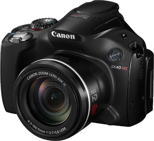
Canon SX40 HS. Source: Photoxels
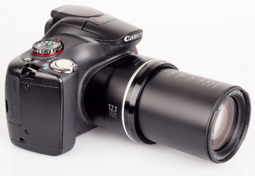
Canon SX40 HS, showing the maximum lens reach. Source: ePHOTOzine
Identified Problems
Early on, I identified the first problem: any camera's data cable ends in a USB type A, and the Raspberry Pi Zero (both the original model and the 2 W) only has one micro USB type B port for data. In my home tests, I used an OTG (On The Go) adapter to connect the camera, but I would need a more reliable solution for the prototype and final product.

Example of a generic USB OTG cable. Not very reliable. Source: Amazon
Example of a shim-type USB OTG adapter, more reliable. The one I used. Source: RaspberryPi.dk
The second problem was powering the Raspberry itself. We had agreed that a powerbank would be used, but the cable would also need to be micro USB type B. So it would be ideal if we could switch to the new type C standard, which is becoming increasingly popular and easy to find.
The third and not-quite-a-problem issue would be connecting the GPIO pin to the device to switch the camera's USB connection. If the prototype were shield/HAT type, the signal could be sent through the pins provided in the board design (following the HAT standard, with the "new" 40-pin layout). However, choosing this path, I would still need to solve the connection of the two micro B USBs. So a decision needed to be made here.
The Prototype
Within a few hours, after wasting time (unfortunately) with PCB manufacturing solutions here in Brazil, I turned to JLCPCB to manufacture the board. This way, I designed exactly what I wanted, and the benefit of using this platform would be having the entire solution in one place: the online CAD (computer-aided design) platform to design the board, the selection of available components to be used, the printed circuit board fabrication, and the component assembly on it.
Since we had wasted a lot of time waiting for a response from a Brazilian manufacturer, I received carte blanche to submit the entire project to be manufactured in China. Initially, I covered all costs, but would be reimbursed later.
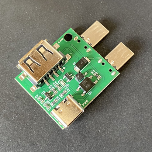
Top view of the board
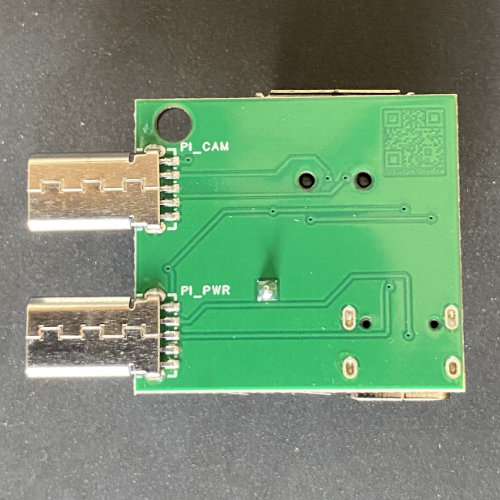
Bottom view of the board
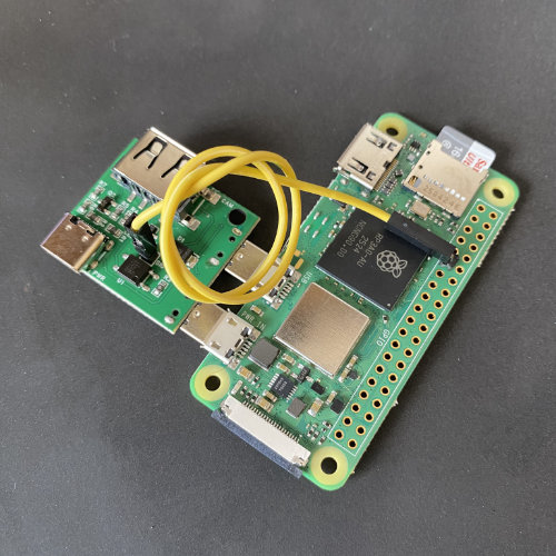
USB board connected to the Raspberry Pi
The prototype board consisted of an embedded OTG adapter with external switching (via pin, to the GPIO), a USB type C connector for powering the Raspberry Pi, and an LED to indicate circuit switching.
Next Steps
As of the publication date of this post, the board has not yet been submitted to field testing by the client company, but it is in an advanced stage of enclosure development to then be tested in the field.
Some improvement points were identified for a next version. Therefore, the next units will be manufactured with these improvements already implemented.